To maximize the advantage of renewable resources, the operation and control of the distributed energy resource (DER) and distributed energy management systems (DERMS) must be integrated into the legacy operational infrastructure of the distribution management and control systems within the utility namely the SCADA/DMS/OMS/ADMS. Centralized coordination and optimized control of all resources is used to improve the feeder's power factor, reducing the feeder's operating costs. Dynamically optimized adjustment of the feeder's voltage profile will improve the feeder's energy transfer capability and quality of service. Remotely controlled switching enables self-healing and load transfer operation to improve reliability and resiliency. When coordinated, these improved feeder conditions will benefit the feeder operations and renewable resource injection, enabling all DERs to achieve their maximum generation capability at the point of common coupling to the feeder. The benefits of organized control of all feeder resources, including renewables, are substantial.
Many utilities have embarked on pilot programs to engage renewable resources, to gain a better understanding of their effectiveness and the cost of implementation. Federal and state government grants are offered to encourage investment in new DER implementation. Unfortunately, uncontrolled, independent deployment leads to an array of heterogeneous equipment, making integration a challenge. A flexible architecture needs to be deployed in which to manage the various components seamlessly, without massive and/or expensive changes to legacy systems. The development and adoption of standards is an important step in normalizing the communication between the various devices that are necessary to accomplish the coordinated optimization of the feeder controlling devices, such as:
- Load tap changer
- Voltage regulator
- Capacitor
- DER / Inverter controller
- Load control
Integration Considerations
Utility control centers perform their basic functions using SCADA and outage management systems (OMS). SCADA performs critical real-time data collection, alarm and event management with operator-initiated remote control. SCADA manages bilateral, secure communications using multiple master/slave protocols with the substation and feeder devices through RTUs, IEDs and controllers. OMS evolved from geographical information systems (GIS), where the detailed network graphic was extended to become a connectivity model, primarily used for troubleshooting outages and crew dispatch. The OMS also manages customer call handling related to outages.
Few utilities have a DMS or ADMS to perform advanced load flow-based distribution network analysis with automation. The distinction between DMS and ADMS is a result of their evolution. If the advanced network load flow functions evolved from the OMS, it is labelled an ADMS. If the advanced network load flow functions evolved from the real-time SCADA platform, it is labeled DMS. Some DMS systems have added outage management and call management to the network load flow model. The goal is to minimize an increasing array of systems. The functional layers of typical distribution system architectures are depicted in figure 1. The gaps between systems increase integration challenges.
Because of its origins, an ADMS system requires a separate SCADA system to perform the basic body functions of retrieving network data, whereas DMS evolved from the SCADA platform into an integrated system. It should be noted that some DMS systems, with OMS, may also be labeled ADMS, purportedly to minimize confusion.
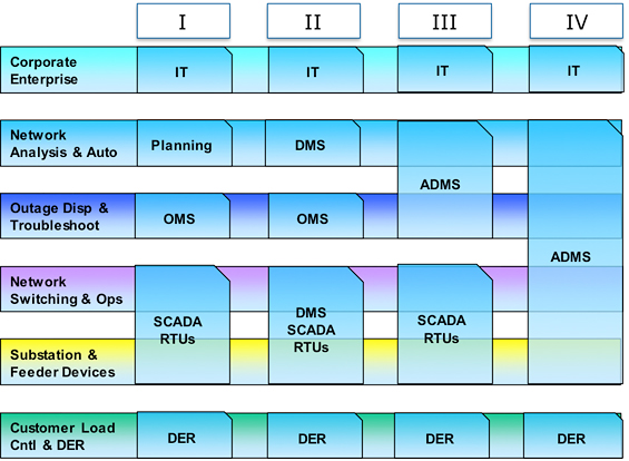
Figure 1: Typical SCADA / OMS / DMS / ADMS Utility Systems
Renewable Integration on Legacy Architectures
The optimization of renewable resource management requires DMS or ADMS analysis capability. If few utilities possess the advanced model and analysis capability with control of necessary field devices, few are prepared to support the new technology without what is perceived as a massive and expensive fork lift replacement of legacy systems. This is impractical.
A similar roadblock was overcome when implementing self-healing technology on a utility which ran SCADA and OMS. The same impediment appeared to prevent automation. However, Georgia Power very successfully implemented self-healing automation, adding an application layer of closed loop self-healing automation between the RTU layer and the legacy SCADA/OMS layers. The application processor performed the closed loop automation without a DMS. It detected and isolated the faults, then performed switching to isolate and restore unfaulted upstream and downstream line sections. The switching solution performs complex load transfers and a return to normal' configuration once the faults are removed. The application layer performs its function transparent to the SCADA and OMS by replicating the RTU in terms of protocol, addressing, station point configuration, data acquisition and control without changes to the legacy SCADA. The following figure describes the added layer of the distributed application processor(s).
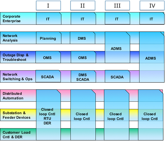
Figure 2: Architecture of the Added Distributed Application Processor
It is proposed that the same architecture should be extended to add to the model that supports self-healing the functions of integrated Volt VAr control, DER feeder injection test for real-time violations, DER inverter control to maximize reactive and voltage control and dynamic emergency load transfer. In effect, the application processor will perform the DERMS functionality, utilizing the existing substation and feeder devices.
Expansion of DER / DERMS
The major advantage of this approach is that an application processor layer can be targeted to specific feeders, such as those with DERs, without altering the legacy systems of the layers above and below the application processor layer. New feeder models can be added incrementally or by implementing islands' consisting of a group of feeders and substations. The user defines the island size. Georgia Power began with a pilot project and has since incrementally expanded automation to over 700 feeders serving more than 1.4 million meters. They continue to incrementally expand the scope each week.
The application processor(s) can be geographically distributed or centralized. Ruggedized versions have been run in harsh substation environments.
Visualization
The application processor's operating system includes a full function graphical user interface with enhanced security. Normally the HMI is not needed, and therefore is typically not used. In an emergency, however, the resiliency of the proposed application layer is that it offers another independent mode of automation and potential operation with the inherent HMI, offering an additional degree of isolation and verification of results.
Summary
The proposed distributed architecture is field-proven, with minimal implementation effort and disruption. It offers utilities the option of adding advanced automation with renewable integration and management with minimal disruption to legacy systems.
For more information
Canada
Gary Ockwell
P.E.
Gary L. Ockwell, P.E., holds a B.S., EE Degree from University of Saskatchewan. From 1973 to 1985, he worked for SaskPower Corporation as a manager of the control department and project manager for the gas and electric system control project. From 1985 to 1995, he worked as a product manager for Harris Controls Division, working with transmission EMS. He joined Advanced Control Systems in 1995, working on both EMS and DMS. From 2007 to the present, he has held the position of Chief Technology Officer. Mr. Ockwell has authored and co-authored two dozen papers and articles for industry conference and publications over the last 10 years. He is an IEEE/PES member.
