
In the previous articles, we discussed how to maximize the benefits of DERMS in a Smart Grid environment and how to leverage a distributed architecture to improve renewable resource effectiveness. This article builds on the previous discussions, describing the operational role from minimal initial DERMS deployment to the evolutionary transition of an extensive DERMS operation.
Autonomous Versus Operator-directed DERMS
The Smart Grid encompasses a suite of integrated network functions. Each function comprises a toolset of applications. For example, centralized self-healing embodies topology processor, load estimator, fault isolation, load flow analysis, optimal network reconfiguration and emergency load transfer all of which are sustained by a three-phase network model. Supporting functions include complex operator graphics and switch management. However, some utilities perform model-driven self-healing functionality in a decentralized autonomous mode like a protection relay, without an operator's input. Decentralized automation dramatically reduces the cost and complexity of the application and the supplemental operator functions. By analogy, if by design one removes a pilot from the cockpit of a fighter jet, what remains is a radically smaller and relatively inexpensive drone. It gets the job done by simplifying the mission parameters.
DERMS deployment is the same. DERMS functionality surrounds a suite of applications that complement the DERMS mission. Like self-healing, DERMS can be deployed under two fundamental modes: with or without operator involvement.
Operator-supported Architecture
The decision as to whether DERMS runs autonomously or in operator advisory mode will dictate the architectural options. Since there are tradeoffs, the utility must decide their preference. If, for maximum flexibility, the operator is integral to the operation, the architecture is likely centralized. This will increase communication requirements, while reducing options for leveraging the advantages of the cost of a distributed architecture. Operator-directed DERMS involves sophisticated graphics with complex modeling to display the contributory data that enable the operator to investigate and select the optimal resolution.
Operator-supported Functions
All DERMS deployment begins modestly; however, expansion must be considered when DERMS growth produces network complications due to excessive injection. Resolution of the violations will involve emergency operator input to enact network adjustments. The toolset of applications comprising a centralized DERMS that enable the operator to analyze and optimize the operation include:
- The feeders sustaining DERMS injection must be modelled by a three-phase unbalanced load flow with load and state estimator. D-SCADA systems cannot support this basic requirement without a network model.
- Dynamic feeder visualization is vital to the operator to colorize the network map with empirical values to display the operating state. The centralized map is typically produced from the GIS via a complex and involved process. The effort to build the entire map may be an excessive exercise during the early phase when few feeders support DERMS.
- Whether switching is automatic or performed manually, Topology Processor reflects the operational state of the network as switched. It is critical that all applications use the same network model and adapt in real-time to changes.
- DERMS generation forecast is used to determine the magnitude of forecasted injection with regards to amount and duration. The location of the points of common coupling is defined in the model and is essential to subsequent injection analysis.
- Forecasted and real-time injection analysis is performed to predetermine if excessive collective DERMS injection will likely cause a feeder problem. The optimum operational objective is to enable the maximum amount of injection at all points of injection. However, if the amount of injection adversely diminishes the reliability of the feeder, then operator resolution is required. Calculation for violations is performed under the forecast and is again checked in real-time.
- Feeder reconfiguration is a necessary consideration only if it is determined that the planned injection will be excessive, threatening the viability of the feeder and causing voltage violations and a resultant loss of quality of power served to the feeder loads. The objective of feeder reconfiguration is to perform emergency load and DERMS transfer to alternate feeders. If needed, this determination must be known in advance if the optimal reconfiguration of the feeder includes manual switching. If manual switching is to be performed, it is best planned up to 24 hours in advance.
- Calculation of the maximum allowable injection, before violations occur, must be determined to scale back the DERMS output to acceptable values. However, derating the DERMS, if imposed, will require additional processes and controls.
The role of the operator in the loop of the DERMS analysis and automation becomes important during the planned or forecasted injection analysis. If the amount of potential DERMS injection threatens the operational parameters of the feeder, then the operator's role is pivotal. When the degree of injection is large, then advanced visualization and analysis applications to determine the best mitigation plan are substantial operator tools.
If feeder reconfiguration is needed to avoid violations caused by DERMS injection, then supplemental operator tools can provide a more efficient and timely solution. For example, integrated switch plan management, tightly coupled with crew mobile applications, will efficiently perform changes to accommodate DERMS.
Non-Operator - Full Automation DERMS
For most DERMS operations, the amount of feeder injection is minimal and the DERMS island can be operated in full automatic mode. The reduction in cost and operational complexity, as well as simplifying active operator participation and training, is an advantage.
Emergency load transfer is a primary automation function. Referring to the application list for centralized operations, the injection forecast application may be eliminated if no foreseen scenario will result in violations. However, as DERMS deployment grows within a feeder and the real-time injection analysis foresees impending violations, an emergency load transfer application will then become necessary. Load transfer with boundaries can be automatically performed without an operator.
The need for an emergency load transfer, caused by ancillary functions, may arise sooner than expected. For example, following a fault, self-healing automation may reconfigure a feeder to restore power. Hours later, however, a load change in the unexpected, or abnormal configuration may create a situation where emergency load transfer is indispensable. Likewise, calculation of the maximum allowable injection is not needed under minimal deployment.
Generally, integrated Volt VAr optimization and control to flatten and lower the feeder voltage profile are very beneficial and should be integrated with DERMS automation from the start.
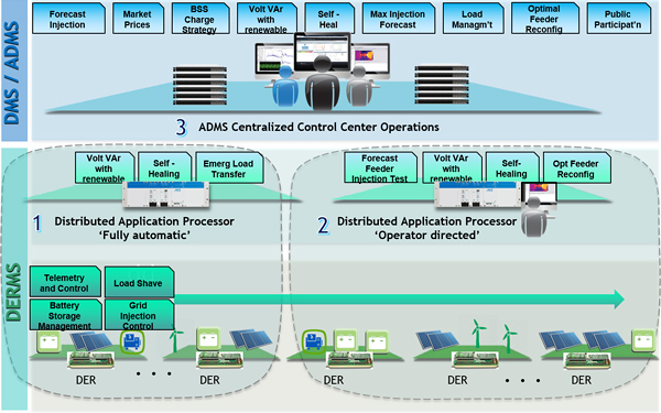
Figure: Three step evolution of DERMS Deployment
Summary
An attractive phased implementation of the role out of DERMS can begin with a low cost, fully automatic, functionally simplified distributed architecture. The low cost and practical approach is easily deployable and expandable for years of growth before the complexity of massive DERMS injection needs to be addressed by the control center. As DERMS deployment increases, a transition is needed to a more capable, operator-centric, centralized solution.
The selection of a DERMS program should consider the operational needs and the ability of the selected technology to cleanly evolve from the initial phases to the expanded deployment.
For more information
Canada
Gary Ockwell
P.E.
Gary L. Ockwell, P.E., holds a B.S., EE Degree from University of Saskatchewan. From 1973 to 1985, he worked for SaskPower Corporation as a manager of the control department and project manager for the gas and electric system control project. From 1985 to 1995, he worked as a product manager for Harris Controls Division, working with transmission EMS. He joined Advanced Control Systems in 1995, working on both EMS and DMS. From 2007 to the present, he has held the position of Chief Technology Officer. Mr. Ockwell has authored and co-authored two dozen papers and articles for industry conference and publications over the last 10 years. He is an IEEE/PES member.
